Before getting into the mechanics below outlining the data and steps necessary to calculate the proper spring rate, we want to point out a few things as follows:
- Please note that Viking has a very detailed spring rate calculator and an extensive database of vehicle specifications in order to assist you in determining the ideal spring rate for your specific set-up and intended use. Please call for assistance.
- The intended use of the vehicle is critical. An often overlooked concept when discussing spring rate is natural frequency. For example, we may get a call where an individual states that he needs a 500 lb. spring because that is what his buddy runs and it works great. Well, if that person's car is a clone of his buddy's car, that may very well be the case. However, in reality cars are set-up / finished differently. In many cases, the example given would actually involve two totally different cars. That is why it is important to match the spring natural frequency on his buddy's car, not the rate. We have a database of targeted natural frequencies for different vehicles, uses, etc. Some of these targets result in throwing some of the discussion below out the window. For instance, certain competitive pro-touring set-ups may result in a natural frequency where the springs unload at full droop making the shock preload a different discussion. If this is the case, we recommend a 7946-101 take-up spring kit.
- General rule of thumb: The shorter the spring, the higher the rate.This is generally the case as the shorter spring will obviously have less available travel. As such, the spring rate needs to change in order to lessen the spring preload at ride height to ensure sufficient compression travel before reaching solid height. If you increase the rate on the car with all others factors being equal, the natural frequency goes up. So when considering the mounting style of a shock, the spring length required should be considered to make sure it meets the desired goals. For example, some people will convert an upper mount on a front shock for a C5/C6 corvette to an eyelet. This results in a shorter shock and a shorter spring. A shock with less stroke and a higher natural frequency may work out great for a competitive handling situation. However, for a person who just wants to cruise, this may not be optimal. It is important to understand how any potential changes will effect the spring rates / natural frequencies.
- The shock valving must match your desired spring rate. A person with a handling application may determine that an 800 lb. front rate is needed to get to the desired natural frequency. This spring must be matched with a shock that has the valving to control that 800 lb. spring.
How to Determine Spring Rate:
In order to correctly determine the optimal spring rate for
your vehicle, it is necessary to calculate the force (in pounds) required to
get your vehicle to the proper ride height. Before getting into the specific
formulas, the sprung corner weight of the vehicle must be determined, along
with the desired preload on the coil spring at ride height. From there the rate of
spring can be selected based on the ride the individual desires; the
availability of adjustment on the coil-over shock; and the ability of the coil
spring to provide enough travel.
Note: Viking designed its coil-over shocks with the longest
threads in the industry providing for the most adjustability. This increase in adjustability
is only useful if the coil spring has enough travel to utilize this large range
of adjustment. Viking coil springs are designed to provide for the maximum level
of travel at the lightest weight, giving the Viking coil-over shock / coil
spring combination the largest adjustment
range in the industry.
Sprung Corner Weight (SCW):
Ideally, the individual corner weights of the vehicle would
be determined by utilizing a scale. If only the total front or rear weight is
known, simply cut it in half to estimate the weight at each corner. Be sure to
account for the driver, passengers, and cargo that will be included when the
vehicle is being driven. Next, the corner weight must be reduced by the
unsprung weight to derive the sprung corner weight (SCW). The unsprung weight
is the vehicle weight that is not supported by the springs. These types of
components include the wheel/tire assembly; the brake components, such as
rotors, calipers, and pads or the brake drums, shoes, and related components;
steering knuckles; wheel bearings; and the axle housing, ring & pinion,
axle, differential, etc. There is also a hybrid weight category for some
components where the definition is not clear and concise. These include the
shock absorbers, coil springs, leaf springs, upper and lower control arms
(front and/or rear), trailing arm,
ladder bar, panhard bar, and driveshaft, to name a few. There is a general
50/50 rule that states 50 percent of the weight of hybrid components is
considered unsprung and 50% of the weight is considered sprung. While the
accuracy of this can be and is debated, it is often used for simplicity. As you
can see, this calculation can prove cumbersome and difficult to determine. In
general, the corner unsprung weight on a vehicle will often lie between 75 and
150 pounds. All changes made to the vehicle must be considered when estimating
the unsprung corner weight based on the above given range. Before moving on
from this topic, it is important to discuss the on-going debates surrounding
the benefits of reducing unsprung or sprung weight. While it is argued whether
or not reducing unsprung weight is more beneficial than reducing sprung weight
and what exactly the benefits are for straight-line improvements versus
cornering, it is agreed upon that reducing unsprung or sprung weight will
improve handling and performance, period. This is why Viking designed its coil
spring line to provide the greatest travel at the lightest weight. Viking
springs are often more than 25% lighter than the competitions' springs. That is
like getting four Viking springs on your vehicle for the weight of three of the
competitions' springs. Work is often done to save ounces, which is important,
as everything adds up. However, Viking springs give you an opportunity to save
pounds!
Spring Preload (SPL):
When a vehicle is at ride height, there will be a certain
amount of preload on the spring. Most springs have a linear rate. For example, a
200 pound spring rate means that it will take 200 pounds to compress the spring
1 inch. It will take an additional 200 pounds to compress the spring a second
inch, and so forth. This would mean a 200 pound spring that is compressed two
inches at the vehicle's ride height would be supporting 400 pounds, as long as
it was mounted straight up and down. The amount of spring preload will also
depend on the stroke of the shock absorber. Recommended ride heights generally
fall within 40% to 60% of the stroke available for either compression or
rebound of the shock absorber. Ideal set-ups will fall closer to having 60%
available for compression and 40% available for rebound. Sometimes a taller
coil spring will be used where the spring will need to be compressed in order
to mount it onto the shock absorber prior to installation in the vehicle. If
this is the case, this amount of preload will need to be accounted for when
determining spring rate. Using the theory that 60% will be available for
compression, for a shock absorber that has a 5" stroke, the shock and
therefore the spring, will need to be compressed 2" in order to have 60%
or 3" of the stroke available for compression when the vehicle is at ride
height. For a shock with an 9.00" stroke, the spring would be compressed
3.60", and so forth. An additional 1" of compression should be added for
raising the spring nut up the coil-over shock absorber, which will allow for
tuning in either direction. After the amount of spring compression is
determined based on the stroke of the shock, a lighter or heavier spring rate may be utilized in order to satisfy the individual's desired use. The change in the spring compression can be accounted for in where the spring seat nut adjustment ends up on the coil-over
shock absorber.
Correction Factor for Spring Mounting Angle (CF):
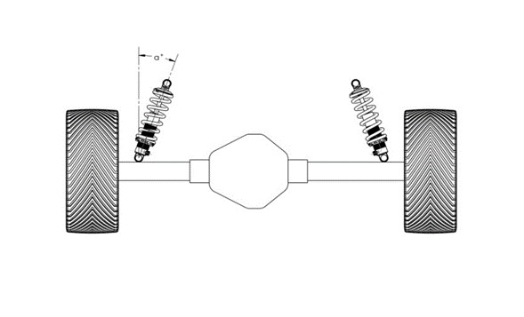
If the coil-over shock absorbers, and therefore
your coil springs, are mounted at an angle, a heavier spring will be needed to
support the same weight. A correction factor will need to be applied to the
spring rate as determined if the spring is installed without a mounting angle
(i.e. straight up). Use the following chart to determine the correction factor
to apply based on the mounting angle:
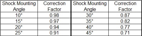
Once the proper correction factor is determined, simply
divide the calculated spring rate with no mounting angle by the correction
factor. For example, if your shock is mounted at a 20° angle and the spring
rate without a mounting angle was determined to be 200 pounds, the proper
spring rate for this application would be 225 pounds (200/.88=227). The
formulas will vary depending on whether you have a straight axle or independent
suspension application.
For straight axles, the spring rate is calculated as
follows:
Step 1: Determine the
sprung corner weight (SCW) as discussed.
Step 2: Determine the
spring preload as discussed.
Step 3: Divide the
sprung corner weight by the spring preload. SCW/SPL=calculated spring rate
(CSR)
Step 4: Divide the
calculated spring rate by the correction factor (CF). If there is no mounting
angle, the correction factor equals 1 so the calculated spring rate will equal
the actual spring rate. CSR/CF=actual spring rate (ASR)
Step 5: Determine a
spring rate for the application desired. The rate in step (4) provides for an
excellent ride and terrific handling. In general, a range of +/- 20% from this
rate can be utilized. This will allow for lighter rate applications, such as
drag racing to heavier rate applications, such as road racing.
For independent suspensions, the spring rate is calculated
as follows:
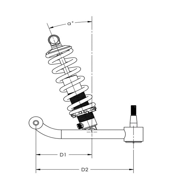
D1: The distance
from the pivot point of the control arm to the mounting point of the
shock/spring.
D2: The distance
from the pivot point of the control arm to the center of the ball joint.
Step 1: Determine the
sprung corner weight (SCW) as discussed.
Step 2: Determine the
spring preload as discussed.
Step 3: Divide D1 by D2
to calculate the motion ratio (MR).
Step 4: Divide the
sprung corner weight by the motion ratio. SCW/MR=required spring force (RSF)
Step 5: Divide the
required spring force by the spring preload. RSF/SPL=calculated spring rate
(CSR)
Step 6: Divide the
calculated spring rate by the correction factor (CF). If there is no mounting
angle, the correction factor equals 1 so the calculated spring rate will equal
the actual spring rate. CSR/CF=actual spring rate (ASR)
Step 7: Determine a
spring rate for the application desired. The rate in step (6) provides for an
excellent ride and terrific handling. In general, a range of +/- 20% from this
rate can be utilized. This will allow for lighter rate applications, such as
drag racing to heavier rate applications, such as road racing.
|
